
UNIT II
Introduction,
Polymers, Polymerization, Addition of Polymers, Plastics, Types of plastics,
Properties of Plastics, Processing of Thermoplastic Plastics, Injection
Moulding, Extrusion Process, Sheet forming processes, Processing of
Thermosetting Plastics, Compression Moulding, Transfer Moulding, Casting of
Plastics, Machining of plastics, other processing methods of plastics
Introduction, casting,
thread chasing, Thread Rolling, Die Threading and Tapping, Thread Milling,
Thread Measurement and Inspection
2 INTRODUCTION OF PLASTICS AND
POLYMERS
Plastics
belong to the family of organic materials. Organic materials are those materials,
which are derived directly from carbon. They consist of carbon chemically combined with hydrogen, oxygen
and other non-metallic substances, and their structures, in most cases, are
fairly complex. The large and diverse organic group includes the natural
materials: wood, coal, petroleum, natural rubber, animal fibers and food, which
have biological origins. Synthetics include the large group of solvents,
adhesives, synthetic fiber- s, rubbers, plastics, explosives, lubricants, dyes,
soaps and cutting oils etc. Which have no biological origins? Of them, plastics
and synthetic rubbers are termed as “polymers”.
2.1 POLYMERS
The term
“polymer” is derived from the two Greek words: poly, meaning “many“, and meros
meaning “parts“ or “units”. Thus polymers are composed of a large number of
repeating units (small molecules) called monomers are joined together
end-to-end in a polymerization reaction. A polymer is, therefore, made up of
thousands of monomers joined tog -ether to form a large molecule of colloidal
dimension, called macromolecule. The unique characteristic of a polymer is that
each molecule is either a ling chain or a network of repeating u -nits all
covalently bonded together. Polymers are molecular materials and are generally
noncrystalline solids at ordinary temperature, but pass through a viscous stage
in course of their formation when, shaping is readily carried out.
The most common polymers are those made from compounds of carbon, but
polymers can also be made form inorganic chemicals such as silicates and
silicones. The naturally occurring polymers include: protein, cellulose,
resins, starch, shellac and lignin. They are commonly found in leather, fur,
wool, cotton, silk, rubber, rope, wood and many others. There are also
synthetic polymers such as polyethylene, polystyrene, nylon, terylene, dacron
etc., termed under plastics, fibers and elastomers. Their properties are
superior to those of the naturally occurring counter- parts. Our concern, here,
is therefore, with synthetic polymers, also called plastics (again from Greek
plastics, derived from plassein: to form, to mould) or resins.
2.2 POLYMERIZATION
The process of linking together of monomers, that is, of obtaining
macro -molecules is called “polymerization”. It can be achieved by one of the
two processing techniques:
(a) Addition Polymerization. In addition or chain polymerization
under condition of temperature and
pressure and in the Presence of a catalyst called an initiator, the polymer is
produced by adding a second monomer to the first, then a third monomer to this
dimmer, and a fourth to the trimmer, and so on until the long polymer chain is
terminated. Polyethylene is produced by the addition polymerization of the
addition polymerization of ethylene monomers. This linear polymer can also be
converted to a branched polymer by removing a side group and replacing it with
a chain. It many such branches are formed, a network structure results.
“Co-polymerization” is the
addition polymerization of two or more different monomers. Many monomers will
not polymerize with themselves, but will copolymerize with other compounds.
(b) Condensation
polymerization. In this process, two or more reacting compounds may be involved and there is a repetitive
elimination of smaller molecules, to form a by-product for example, in the case
of phenol formaldehyde (bakelite), the compounds are: formaldehyde and phenol.
Metacresol acts as a catalyst and the by- product is water. The structure of
the ‘mer’ is more complex. Also, there is the growth perpendicular to the direction of chain.
This is called ‘cross-linking’.
Size of a Polymer. The polymer chemist can control the average length
of the molecules by terminating the reaction. Thus, the molecular weight (the
average weight, in grams, of 6.02×10²³ molecules) or degree of
polymerization, D.P., (the number of mers in the average molecule) can be
controlled. For example, the length of molecules may range from some 700 repeat
units in low-density polyethylene to 1,70,000 repeat units in ultrahigh
molecule are weight polyethylene.
2.3 ADDITIONS TO POLYMERS
The properties of polymers can be
further modified by the addition of agents, which are basically of two types.
Those that enter the molecular structure are usually called “additives”,
whereas those that form a clearly defined second phase are called “fillers”.
- Plasticizers. Plasticizers are liquids of high boiling point and low molecular weight, which are added to improve the plastic behavior of the polymer. The board role of a plasticizer is to separate the macro- molecules of the polymer, that is, making deformation easier. They are essentially oily in nature. Organic solvents, resins and even water are used as plasticizers.
- Fillers. Filler is used to economize on the quantity of polymer required and / or to vary the properties to some extent, for example, mechanical strength, electrical resistance etc. Filler, whose function is to increase mechanical strength, is termed “reinforcing filler”. A filler is commonly fibrous in natures and is chemically inert with respect to the polymer with Which it is to be used? Common fillers are wood flour, cellulose, cotton flock, and paper (for improving mechanical strength); mica and asbestos (for heat resistance); talc (for acid resistance).Wood flour is general purpose filler. It improves mould ability, lowers the cost with fairly improved strength of the plastics. Mica also imparts excellent electrical properties to plastics and results in low moisture absorption. The commonly used “reinforcing filler agents” with plastics are: fibers/filaments of glass, aramid, graphite or boron. Reinforcing by metal and glass fibers make plastics strong, flexible and light materials such as used in bullet proof vests. Cotton fibres improve toughness. Carbon fibers are used for high performance installations such as aircrafts etc. requiring high strength and stiffness.
- Catalysts. These are usually added to promote faster and more complete polymerization and as such they are also called ‘accelerators’ and ‘hardeners’ e.g., ester is used as a catalyst for urea formaldehyde.
- Initiators. As the name indicates, the initiators are used to initiate the reaction, that is, to allow polymerization to begin. They stabilize the ends of the reaction sites of the molecular chains. H2O2 is a common initiator
- Dyes and pigments. These are added, in many cases, to impart a desired colour to the material. For example, titanium dioxide is an excellent white pigment; iron oxides give yellow, brown or red colour; carbon black is not only a pigment but also a UV light absorbent. Finely divided calcium carbonate dilutes (extends) the colour and is used in large quantities as low – cost filler.
- Lubricants. Lubricants are added to the polymers for the following purposes: to reduce friction during processing, to prevent parts from sticking to mould walls, to prevent polymer films from sticking to each other and to impart an elegant finish to the final product. Commonly used lubricants include: oils, soaps and waxes.
- Flame-retardants. Most Plastics will ignite at sufficiently high temperatures. The non-inflammability of the plastics can be enhanced either by producing them from less inflammable raw materials or by adding “flame retardants”. The common flame retardants are: compounds of chlorine, bromine and phosphorous.
- Solvents. Solvents are useful for dissolving certain fillers or plasticizers and help in manufacturing by allowing processing in the fluid state. For example, alcohol is added in cellulose nitrate plastics to dissolve camphor. However, subsequently, the solvents must be removed by evaporation.
- Stabilizers and anti-oxidants are added to retard the degradation or polymers due to heat, light and oxidation.
- Elastomers are added to plastics to enhance their elastic properties.
Note. Above, excepting fillers,
all other materials used fall under the category of “Additives”.
2.4 PLASTICS
Polymer can be
divided in to three broad divisions: plastics, fibers and elastomers (polymer
of high elasticity, for example rubber). Synthetic resins are usually referred
to as plastics. Plastic derive their name from the fact that in a certain phase
of their manufacture, they are present in a plastic stage (that is, acquire
plasticity), which makes it possible to impart any desired shape to the product.
Plastics fall in to a category known chemically as high polymers.
Thus,
“plastics” is a term applied to composition consisting of a mixture of high
molecular compounds (synthetic polymers) is fillers, plasticizers, stains and
pigments, lubricating and other substances. Some of the plastics can contain
nothing but resin (for instance, polyethylene, polystyrene).
2.4.1 TYPES OF PLASTICS: Plastics are
classified on the broad basis of whether heat causes them to set
(thermosetting) or causes them to soften and melt (thermoplastic).
2.4.1.1 Thermosetting plastics: These
plastic undergo a no. of chemical changes on heating and cure to infusible and
practically insoluble articles, the chemical change is not reversible
Thermosetting plastics do not soften on reheating and can not be worked. They
rather become harder to completion of any leftover polymerization reaction. The
commonest thermosetting plastics are: alkyds, peroxides, melamines, polyesters,
phenolics and urea.
2.4.1.2 Thermoplastic Plastics: These
plastics soften under heat, harden on cooling, and can be re softened under
heat. Thus, they retain their fusibility, solubility and capability of being
repeatedly shaped. The mechanical properties of these plastics are rather
sensitive to temperature and to sunlight and exposure to temperature may cause
thermal degradation. Common thermoplastics plastics are: acrylics, poly tetra
fluoroethylene (PTFE), polyvinyl chlorides (PVC), nylons, polyethylene,
polystyrene, etc.
Thermosetting
plastics are cross-linked polymers and thermo-plastics are linear and
branched-linear polymers. The method of processing a plastic is determined
largely by whether a plastic is thermosetting or thermoplastics.
2.4.2 PROPERTIES OF PLASTICS: There is
great variety of physico-chemical and mechanical properties and the ease with
which they can be made into various articles have found plastics their wide
application in the engineering and other industries.
- Their comparatively low density substantial mechanical strength and high anti friction properties have enable plastics to be efficiently used as substitute for metals, for example, non-ferrous metals and alloy bronze, lead, tin, babbit etc., for making bearing.
- With certain special properties (silent operation, corrosion resistance etc), plastics can sometimes replace ferrous metals.
- From the production point of view, their main advantage is their relatively low melting points and their ability to flow into a mould.
- Simple processing to obtain machine parts. Generally there is only one production operation required to convert the chemically manufactured plastic into a finished article.
- In mass production, plastics substituted for ferrous metals allow the production costs to be reduced by a factor of 1.5 to 3.5 and for non-ferrous metals by a factor of 5 to 20.
- Good damping capacity and good surface finished of the product.
- The high heat and electric insulation of plastics permits them to be applied in the radio and electrical engineering industries as and substitutes for porcelain, ebonite, shellac, mica, natural rubber, etc.
- Their good chemical stability , when subjected to the action of solvents and certain oxidizing agents, water resistance, gas and steam proof properties, enable plastics to be used as valuable engineering materials in the automo9bile and tractor, ship building and other industries
2.4.3 DISADVANTAGES
- Comparatively higher costs of materials.
- Inability of most plastics to withstand even moderately high temperatures.
The factors
which have determined the rapid growth of polymer materials in the recent past
are:
- Ready availability of the basic raw chemical materials in large quantities and, in general, at the low cost.
- The large no. of available starting materials for their production provide us with an almost continuous spectrum of composition and structure, and hence of mechanical, optical, electrical and thermal properties of the resulting polymers.
- The engineer now has at his disposal many well developed processes and machines to convert (as they from the factory and that he can choose according to the specification of the ultimate product) into useful goods.
2.4.4 PROCESSING OF THERMOPLASTIC PLASTICS
Thermoplastic
can be processed to their final shape by moulding and extrusion processes.
However, extruding is often used as an intermediate processes, for example,
vacuum forming or machining.
2.4.4.1 EXTRUSION PROCESS:
The extrusion process,
in many cases, produces material in an intermediate form for subsequent
reprocessing to its final component form. The process is the same as for
metals, that is, the expulsion of material through a die of the required
cross-section .The earliest extrusion machines were of the ram type. The
cylinder of the machine is filled with prepared plastic and extruded through a
die under the pressure of the ram. The advantages of this machine are:
simplicity in operation and a controlled pressure which can be virtually as
high as required. If the polymer can be plasticized by pressure, then the ram
extruder is advantageous in view of its simplicity. But for plastics which
require heat, the separate pre-processing may be regarded as a drawback.
Another major drawback of this type of machine is reciprocating action of the
ram which is time wasting since the ram must be withdrawn after its power
stroke and a new dolly of material inserted in the container. Also, with many
materials the die orifice must be cleaned between each working stroke.


Fig. 2.1 Screw Extruding Machine
Now a days, the ram machine is
mainly used for “wet extrusion” that is for extruding plastics which have been
softened by the addition of solvents. Although useful in homogenizing materials
which contain hard inclusions, wet extrusion has the disadvantage of producing
a component from which the solvent has to be remolds.
For the extrusion of the
plastics, single-screw machine has completely replaced the ram type machine.
There are two basic types of screw extrudes: the melt extruder and the
plasticizing extruder. In the former, the material is delivered to the extruder
already melted and thus the function of the extruder is merely to push the
material to the die and through the orifice. In the plasticizing extruder the
material is in the form of granules or particle and so the extrude has to
compress and work it until it melts before delivering it, under pressure, to
the die orifice.
Complex shapes with constant
cross sections can be extruded with relatively inexpensive tooling. The
extruded product can be coiled or cut into desired lengths.
2.4.4.2 SHEET –FORMING PROCESS:
Many plastic articles are formed from
sheet. The process resembles those for metals, but requires very low forces.
Even atmospheric pressure may be sufficient. In “Drape Forming”, the sheet is
heated to a moderate temperature. It is then clamped at the edges and stretch –
formed over a die. One of the encountered is that the portion of sheet first
touching the die will be chilled and remain thicker than the rest. This is
overcome or minimized by blowing hot air between the sheet and the die.

Fig. 2.2(a) Principle of Vacuum Forming Process

2.4.5 PROCESSING OF THERMOSETTING PLASTICS
Compression molding and transfer
molding are the most common methods of processing thermosetting plastics.
Although, suitable for thermoplastics also, the main application of these
methods is to thermo sets.
2.4.5.1
COMPRESSION MOULDING:

Fig. 2.3 Compression Moulding
Compression moulding is the
equivalent of closed-die forging. In this process, a premature quantity of
plastic in the form of plastics or briquettes is placed in heated mould and
compressed at suitable pressure and temperature. Hydraulic pressure usually
employed to provide the pressure (which may range from 20 to 30 MPa or even
higher up to 80 MPa in same case) for compressing the plastic compound. Other
equipment, such as friction and presses, can also be used. The object of
compression moulding is to bring the plastic to virtually molten state. Thus
the process is, effectively, forming from the liquid state, the material being
healed in the mould until the curing stage is over when polymerization is
complete. The process is rather slow with the phenolics and urea resin, but
some of the newer resins have shorter curing time and this has improved the
production rates appreciably.
When the plastic is completely trapped between the male and female die, it is called as” positive mould”. Cluster tolerances can be held if a small flash is allowed to extrude, usually along the male die perimeter in “semi positive moulds”. More plastics is lost in “flash moulds”, similar to those used in impression-die forging.
When the plastic is completely trapped between the male and female die, it is called as” positive mould”. Cluster tolerances can be held if a small flash is allowed to extrude, usually along the male die perimeter in “semi positive moulds”. More plastics is lost in “flash moulds”, similar to those used in impression-die forging.
Typical product application are:
disches, handles, container caps, fitting,. Electrical and electronic
components, washing machine agitators and housing etc.
2.4.5.2
TRANSFER MOULDING:

Fig. 2.4 Transfer Moulding
Transfer moulding is a
modification of compression moulding in which the moulding is first placed in
separate chamber (transfer pot), from which it pushed through an orifice into
the mould cavity as the mould closes. The material to be moulded is often
preheated by radio frequency methods and, where it is desired to improve toughness
and strength, reinforcing fillers may be used.
The process has got following
advantages:
1. There is little pressure
inside the mould cavity until it is completely filled, at which stage the full liquid
pressure is transmitted.
2. The plastic acquires uniform
temperature and properties in the transfer pot prior to transfer .The plastic
is further heated by sheering through the orifice, viscosity is reduced, and
the plastic fills the intricate mould cavities.
3. It scores over normal
compression moulding in that presses can be used, since; heating of plastic is
affected, not by press itself, but by a simple heating jacket round the
transfer chamber.
2.4.6 CASTINGS OF
PLASTICS:
Casting of plastics in moulds finds application when making parts of
plastic material with a binder but no filler.
It is also used to obtain various kinds of casts thermosetting plastics,
for example, cast carbolite, as well as certain cast thermoplastic material,
such as organic glass, polystyrene and others.
The method is simple and cheap since no expensive tooling or equipment is
required, and no pressure needs to be applied to fabricate the part. There are many variations of the casting
method for plastics:-
(a) By using flexible moulds, very intricate shapes
can be fabricated. The mould is peeled off afterwards.
(b) Using plate glass moulds produces thick plastic
sheets.
(c) Using moving stainless steel belts, which contain
and cool the resin, produces thinner plastic sheets.
(d) Hollow shapes can be obtained by centrifugal
casting of the molten plastic material.
(e) Potting: In this method, the plastic material is cast around an electrical
component, which gets embedded in the plastic material. This is achieved by pouring the molten
plastic material in a housing or case, which is an integral part of the
component and in which the component is repositioned before pouring the
plastic.
(f) Encapsulation: Here, the component is covered with a layer of cooled and solidified
plastic.
(g) Both potting and encapsulation are very important
to the electrical and electronics industry.
The plastic material serves as a dielectric.
(h) Foam
moulding / casting: In this
method a foaming agent is mixed with the plastic resin. The mixture is placed in a mould and
heated. The foaming agent makes the
material to expand (even up to 50 times the original size) to take up the shape
of the mould. The amount of expansion
can be controlled through temperature and time. Both rigid and flexible foamed
plastics can be obtained from thermo-plastics and the thermo-setting
plastics. Rigid construction is used for
structural purposes and flexible for cushioning. Product application include: Shaped packaging
materials for cameras, appliances and electronics etc. insulating blocks, food
containers and Styrofoam cups.
2.4.7 MACHINING
OF PLASTICS:
Plastic can be machined, but in most cases, machining of plastics is not
required. Moulding and forming methods
can obtain acceptable surface quality and dimensional accuracy. However, there are certain plastics like PTFE
(Polytetra fluoroethylene) which are sintered products and are not mould able
by usual techniques, as they do not melt. For such “thermo stable plastics”
machining is a viable alternative to moulding.
The machining of plastics (by operation such as turning, drilling and
milling) has special features due primarily to the structure of the
material. It also depends upon the
binder upon the binder and the filler and the method of moulding the component.
For example, the machining of thermosetting plastics allows optimum cutting
variables and tool geometry to be employed because these do not soften on
heating, whereas thermoplastic resins soften under heat. The permissible
maximum temperature in the cutting zone is 1600C for thermo-setting resins and only 600 C to 1000C for
thermoplastics.
Special features of the machining of plastics are:-
- The tendency of certain plastics to splitting.
- High elasticity (40 times as much as that of steels). Therefore, they must be carefully supported, to avoid their deflection during machining.
- Non-homogeneous structure of the material, with components of different hardness. This results in poor surface finish after machining.
- Plastics have a strong abrading action on cutting tools.
- Their low thermal conductivity results in poor heat dissipation from the cutting zone and in over-heating of the cutting edges.
- The intense dust formation, especially for thermosetting plastics, makes it necessary to use special dust -removing devices.
- The hygro scopicity of plastics excludes the use of liquid cutting fluids. Compressed air is commonly used for cooling.
- Reinforced plastics are very difficult to machine.
Plastics can be machined with H.S.S. and cemented -carbide tools. In machining a plastic material with a filler
of glass, quartz or mica type, a satisfactory tool life can be obtained only
with carbide -tipped tools. Only diamond
tools are suitable for turning high-strength plastics of this type. The strength of cast parts of laminate
plastics is 40 to 50 percent less than that of the parts made by compression
moulding. Therefore, higher cutting
speeds and feeds can be used in their machining than for strong thermo-setting
plastics. The main trouble in turning
laminated plastics is the peeling of the surface layer.
The cutting variables are also influenced by the life of cutting tool
which is subject to abrasive wear in machining most engineering plastics. Dulling of the cutting tool leads to a poor
surface finish and to breaking out of the material at the points the cutting tools
enters and leaves the cut. This makes it necessary to use more keenly sharpened
cutting tools for plastics. The need for
sharp cutting edges follows from the high elasticity of plastics.
The selection of cutting variables is also influenced by the low heat
conductivity of the plastics, since, in machining the tool may be within a
closed volume (as in drilling) with no cooling facilities. This may lead to
charring of the machined surface.
The cutting tool angles for machining plastics are made somewhat different
than those of tools for ferrous and non-ferrous metals. The rake angles are
positive and relatively larger. Because
of the visco elastic behavior of thermoplastics, some of the local elastic
deformation is regained when the load is off.
Therefore tools must be made with large relief angles (200 to 300).
Abrasive machining of plastics has many advantages over machining with
metal cutting tools. These include the absence of splitting and crack
formation, and the better surface finish that can be obtained.
In grinding, the contact between the wheel and the surface being ground,
should be as short as possible, to avoid burns.
Organic glass is commonly ground with coated abrasive, applying an ample
amount of water as a coolant. If possible, however, grinding should be replaced
by polishing with a felt, broadcloth or flannel wheel charged with lapping
paste, the process is known as “Buffing”. The buffing wheels are of diameter
250 mm, 40 to 60 mm wide and of speed 2000 rev/min. Medium and fine lapping pastes are used as
the buffing compound for plastics. Laminate fabric base, asbestos-fiber and
glass -fiber laminate can be cut with abrasive wheels (SiC) of grain size 24 to
46 and with a 5% emulsion as the cooling fluid.
2.4.8 OTHER PROCESSING METHODS FOR PLASTICS
1. Calendering: It is an
intermediate process where the extruded plastics sections are reduced to sheet
which may or may not, then be formed to final shape by vacuum forming. It is clear that the calendering process can
be used for thermoplastics and not for thermosetting plastics.
Calendering is some ways similar to rolling process in that the material
is compressed between rolls and emerges as sheet (Fig 2.5a). However, there are differences. There is
appreciable thickening after the material has reached minimum thickness at the
roll gap and the pre-calendered material is not in sheet form, but of
indefinite shape. The method of producing vide sheet and foil is illustrated in
Fig (2.5b). The thermoplastic melt is fed
to a multi roll calendar.
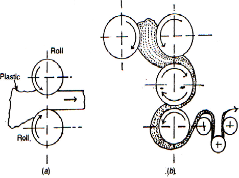
Fig 2.5 Calendering Process
The first roll gap serves as a feeder, the second as a metering device,
and the third roll gap sets the gauge of the gradually cooling plastic which is
then wound, with about 25% stretching onto a drum.
Calendering is a high -production rate (typically 100 m/min) process,
mostly for flexible PVC, for example, upholstery, rainwear, shower curtains,
tapes, etc. and rigid PVC, for example, trays, credit cards, lamination. PVC is also calendered into the well known
transparent film widely used for packaging.
2. Rotational Moulding: In this
process, also called “rotomoulding”, large relatively thin -walled hollow (open
or closed) parts are made. A measured quantity of Polymer powder is placed in a
thin-walled metal would. The mould is closed and is rotated about two mutually
perpendicular axes as it is heated. This
causes the powder of sinter against the mould walls, building up the wall
thickness of the component. At the end
of the heating and sintering operations, the mould is cooled while it is still
rotating. Applying cold water and air to
the outside of the rotating mould does cooling. The rotation is then stopped
and the component is removed. To increase production rates, three moulds at the
end of three arms joined together to the central spindle (just like centrifuge
casting) are used, with one mould for each stage of the process, that is,
load-unload, heat and cool positions.
The process is simple as no pressure is employed and the part is free of
moulded in stresses. The technique is extensively used for the production of
toys in P.V.C. such as boats, horses etc.
Large containers of Polythene (or up to 20,000 liter capacity) and large
components like laminated petrol tanks for motor care are made from polythene (outer
shell) and nylon (inner shell). Other products include: Trash Cans, Boat hulls,
buckets, housings and carrying cases etc.
3. Blow Moulding: In this
process, a hot extruded tube of plastic, called a parison, is placed between
the two part open moulds (Fig 2.6 a).

3D View of Blow Moulding

Fig 2.6 Blow Moulding
The two halves of the mould move towards each other so that the mould
closes over the tube. The tube gets pinched off and welded at the bottom by the
closing
Moulds (Fig. 2.6 b). The tube is then expended by internal pressure,
usually by hot air, which forces the tube against the walls of the mould.
(Fig2.c). The component is cooled and the mould opens to release the component
(Fig. 2d). Typical products applications are: Plastic beverage bottles and
hollow containers.Fig. 2.6
4. Reaction Injection Moulding
(RIM) : The method differs from the conventional injection moulding process in the sense
that it is not molten polymer which is
injected into a mould, but a mixture of
two or more monomers (reactants ) are
forced into a mould cavity. Chemical reaction takes place between the
constituents of the mixture giving off heat to form a plastic polymer, which
solidifies producing a thermo set component.
The major product applications include: Automotive bumpers, and fenders,
thermal insulation for refrigerators and freezers and stiffness for structural
components.
5. Solid State Forming: The term
is a misnomer because the temperature of the polymer is just (100 to 200C) below the melting point of the
polymer. The main operations involved are: Sheet metal techniques such as
stretching, bending and deep drawing. Many food-packaging tubs and containers
are fabricated from Polypropylene.
Forging is also used mainly for producing gears.
6. Cold Forming: All the
cold working methods used for metals can be used for polymers. Filaments and
fibers are produced by “Cold drawing”, that is, continuous stretch
drawing. Conventional rolling can also
be used for producing fibers. In “Cold
pressing” or “Cold moulding”, the raw thermosetting material (or mixed plastic
compounds) are put in the mould and cured in an oven. Pressure applied by the press range from 14
MPa to 84 MPa. The moulds are made of abrasion resistant tool steel. The process is quite economical and the
process cycle is relative short. However, the surface quality and dimensional
accuracy of the part is not very good.
7. Thermoplastic Stamping: Thermoplastic Stamping or matched-die forming is
a method in which thermoplastic polymer sheet at melt temperature is worked
between mating dies. The cycle time is
greatly reduced and the spring back is minimum.
8. Spinning: The extrusion process can be modified to
produce filaments, fibers and yarns. The molten thermoplastic polymer is extruded through a die containing
holes. For obtaining strands, the dies
can be rotated to produce twists and wraps.”
2.5 THREAD
MANUFACTURING
2.5.1
INTRODUCTION
Threads are prime importance to the engineering. These are
used as fasteners, to transmit power and motion and for adjustment. The subject
of thread manufacture has assumed a great significance because of the
ever-increasing demand for high precision fastening devices and power
transmission devices. At present, the threads are manufactured by the following
processes:
1. Casting
2. Thread chasing
3. Thread rolling
4. Die thread and tapping.
5. Thread milling
6. Thread grinding
2.5.2
CASTING
The accuracy and finish of threads made by casting will
depend upon the method of casting. Threads made by sand casting are rough and
are not used much, except sometimes in vises and rough machinery. Threads made
by die casting and permanent mould casting are very accurate and high finish,
if properly made. However, these can be made only of low melting point
non-ferrous metals and, therefore, are not fit for repeated use, being not hard
and durable. Lost wax method can produce highly accurate threads of good
finish. But the method is costly and difficult. Sewing machine vending
machines, typewriter parts and toys may have their threads cast in place by die
casting and permanent mould casting. Such parts are rarely taken apart, so, the
method is very satisfactory. The drawbacks of sand casting can overcome by
using shell molding method. Due to the inherent drawbacks of casting methods of
thread production.
2.5.3
THREAD CHASING
The method of cutting threads with a single point tool on a
center lathe and with a multipoint tool on a turret lathe is called “thread
chasing”. Thread chasing is a form cutting operation, with the form tool
corresponding to the profile of desired thread space.
2.5.3.1
Thread chasing on a center lathe. The first step in cutting
threads on a lathe is to get an accurately shaped and mounted tool. The form
and setting of the tool is checked with the help of a thread template or center
gauge, Fig. The job is either mounted between centers or held in a chuck (for
external threads) and held in a chuck for internal threads. When mounting the
tool in the tool post, it must be ensured that the top of the job, Fig. After
this, the second step is to establish a specific relationship between the
longitudinal movement of the tool parallel to the axis of rotation, and the
rotation, of the job. This will determine the pitch or lead of the thread. This
is achieved with the help of lead screw and a split nut. The two halves of the
split nut are fastened to the carriage. When the nut is closed on to the lead
screw, it acts as a complete nut, and the carriage starts moving as the lead
screw rotates. The lead screw is geared to the spindle and the proper speed
ratio between the two is sit by means of a gear-change box. Therefore, as the
lead screw rotates, the carriage will move a predetermined distance (depending
upon the pitch of lead of the thread) per revolution of the job. The third
requirement an exact predetermined time, for taking successive cuts, so that
the tool enters the helical groove of the cut previously produced; otherwise
the tool may remove some of the desired thread.

Fig 2.7 Center Gauge
This is achieved with the help of
a ‘thread dial’, which is mounted on the carriage and is driven by the lead
screw through a worm gear. The face of the thread dial is graduated into a even
number of full and half divisions, Fig. Whenever the lead screw rotates and the
split nut is not engaged, the thread dial rotates. The split nut must be
engaged when a particular line on the dial face coincides with the zero line.
For cutting even number of threads, the split nut should be engaged when any
line on the dial coincides with zero line, and for cutting odd-number threads, when
and homebred line coincides with zero line.
To start cutting a thread, the
tool is fed inward until it first scratches the surface of the job. The
graduated dial on the cross-slide is noted or set to zero. The split nut is
then engaged and the tool moves over the desired job length. At the end of tool
travel, it is quickly withdrawn by means of cross slide. The spot nut is
disengaged and the carriage is returned to the starting portion, for the next
cut.

Fig 2.8 Setting of Cutting Tool
These successive cuts are
continued until the thread reaches its desired depth (checked on the dial of
cross-slide). The depth of first cut is usually 0. 25 to 0.40 mm. This is
gradually decreased for the successive cuts until for the final finishing cut;
it is usually 0.027 to 0.075 mm. The tool can be fed inward either radially or
at an angle of 29 by swiveling the compound rest, Fig.

Fig. 2.9 Feeding the tool
into the job
The drawback of the first method
is that the absence of side and back rake will not proper cutting except on
brass and cast iron. In the second method, the cutting mainly takes place on
one face of the tool and some side rake can be provided. Also, the chip will
curl more easily. For cutting square, acme and worm threads, the first method
is used. For cutting L.H. threads, the tool is moved from left to right and for
cutting right hand threads; it is moved from right to left. Thread cutting on a
lathe is a slow process, but it is the only process of producing square threads,
as other methods develop interference on the helix.
2.5.3.2
Thread chasing on a turret lathe. The main drawback of cutting
threads on a center lathe is that the operation cannot be done at higher
cutting speeds, since the permissible speed is limited by the quickness with
which the operator can withdraw the cutting tool from the job at the end of a
cut. This drawback is overcome in turret lathe, where thread-chasing attachment
is used to cut the thread. The attachment has no thread dial, which enables the
operation of the machine even by a semi-skilled worker. A simple thread chasing
attachment for a turret lathe is illustrated in Fig. From the headstock of the
machine, power is given to a short lead screw, known as the leader, by means of
change gears. The fed nut and the tool slide are carried on a shaft, which can
be engaged or disengaged to the leader by means of a hand lever. The major
advantage of the arrangement is that the fed nut can be engaged to the leader
at any portion of the work rotation.

Fig. 2.10 Thread Chasing Attachment


2.5.4
THREAD ROLLING
Thread rolling is a cold working
process in which a blank of diameter approximately equal to the pitch diameter
of the required thread, is rolled between hardened steel rolling dies having
the negative counter of the thread to be produced. As the thread shaped ridges
on the dies penetrate the blank material, material is displaced from the bottom
of the thread and forces radially out to form the thread crests. These are
three types of the thread rolling machine:
1.
Reciprocating, flat die machines.
2.
Cylindrical die machines.
3.
Rotary planetary machines, having a rotary die and
one or more stationary concave-die segments.
In the reciprocating, flat die
machine, one die is stationary and the other reciprocating. The part to be
threaded is rolled between the dies, as the moving die reciprocating in
reference to the stationary die. The stroke of the reciprocating die is will
depend upon the diameter of the thread being produced, since during one stroke,
the blank makes are completely revolution and the thread is completely formed.
This is highly versatile machine, since at the same time threading and knurling
can be done on a part of right and left hand threads can be rolled, by
assembling two or three sets of flat dies. This method is mainly used for the
manufacture of commercial bolts and nuts.
In cylindrical die machine, the
part is to be threaded is rolled between rotating cylindrical dies. The machine
can have two rounded dies located diametrically opposite each other, or three
rounds dies usually spaced. This machine is slower than the reciprocating flat
die machine and is more suitable for large sized precision threads and for
short run production. This machine operates with the following motions:
1.
Positive rotation of the both the dies (in a two die
machine) in the same direction.
2.
Radial motion of one of the dies for its rapid
approach, infeed and retraction. This method has the main application of the
threads on taps.


Fig. 2.11 Thread Rolling
In rotary planetary machine, the
job is rolled between a central die that rotates continuously about a fixed
axis, and one or more concave-shaped die segment located adjacent to the
periphery of the rotating die. This being a continuous process is the fastest
method of thread rolling.
2.5.4.1 Advantages of thread rolling
1.
It is the fastest method of producing a thread, with
production rate more than 2000 piece per minute.
2.
Being a chipless forming process (no material
wastage), there is lot of material saving (about 16 to 27 %).
3.
During thread rolling, the material is strained
plastically and is work-hardened, and is, therefore, stronger against both
tension and fatigue, especially the latter.
Increase in tensile strength is form 10 to 20% and
that in fatigue strength is from 10 to 75%
4.
The grain fibers remain continuous and follow the
contous of the threaded surface. Due to his, the threads are less easily
sheared off than machined threads.
5.
The surface of rolled thread is harder than a cut
thread, so wear resistance increases.
6.
Surface finish is better as controlled by the rolls.
7.
Dimensional accuracy is better, as very little wear
occurs on the rolls as it would on a cutting tool.
2.5.5 DIE THREADING AND TAPPING
2.5.5.1 Die Threading. Die threading is a method
of cutting external threads on cylindrical or tapered surfaces by the use of
the solid or self-opening dies. The main advantage of die threading is that it
can be performed along with other operations on turret lathes and on automatics
(in the case of self opening dies).
2.2.5.2 Solid Dies. In principal, a solid consists
of a hardened, threaded nut with several longitudinal grooves cut away and
shaped to provide cutting edges to the remaining portions of the thread. To
facilitate their use from either end, entry chamfers are provided at both the
ends. To cut the threads, the die is screwed on the bar upon which the threads
are to be cut. To move the die along the bar, it is held in stock. This is
rotated manually. To cut a smoother thread and to prolong the life of the die,
a suitable lubricant is used. The solid type dies are used rarely, because they
do not have any adjustment for wear. The solid adjustment can be adjust for
size and wear over a small amount by means of a screw, these dies are made of
carbon or high speed tool steel and can be used on a turret lathes with
suitable holders.

Fig. 2.12 Solid Threading
die
2.2.5.3 Self-opening die heads. The major
drawback of the solid type dies is that they must be unscrewed from the work
piece by reversing the machine spindle, to disengage the die from the work. Due
to this, these dies are not suitable for use on high speed production machines,
for use on high speed production machines, e.g. turret lathes and automatics.
This drawback is overcome by using self-opening die heads. When the required
length is thread is cut, the die open automatically. At the end of the turret
slide travel, the front portion of the dire head continuous to move forward by
a small amount until the chasers in the die head move outward in the body,
under the action of a scroll or a cam. This action clears the chasers from the
cut thread and enables the die head to be withdrawn without reversing the
machine spindle. The die head, while cutting threads may advance its own
guidance once it screws itself along the work, until the die trip opens.
However, for better accuracy, there is increasing use of lead screw guides.
Depending
upon the type of chaser, there are three types of die heads
1.
Radial
2.
Tangent
3.
Circular
Radial chasers can be more
rigidly, supported than other types. These are difficult to resharpen and their
life is short. Tangential chasers give a long life, because the length of the
teeth makes possible a large number of regrinds on the cutting face. Due to
this they are very suitable for heavy duty work and large batch production.
Circular chasers also have a long working life since these can be resharpened a
number of times. All the die-heads can either be stationary or revolving.
When used on automatics, the feed
motion of the die-head is controlled by the cam rise, which can be designed
according. At the end of the return stroke, the dies are closed automatically
when the closing handle strikes a rod. Die-hands are available for cutting
threads from 6.35 mm to 114 diameter and chasers are available for any thread
form.
2.2.5.4 Thread tapping. Taps are the tools for cutting internal
threads. A tap is similar to a threaded bolt, with one to four flutes cut
parallel to its axis. The flutes perform three functions:
1.
Provide cutting edges.
2.
Conduct the cutting fluid to the cutting region, and
3.
Act as channels to carry away the chips formed by the
cutting action.

Fig. 2.13 Self opening die head
The flutes can be straight,
spiral, helical or spiral pointed. Taps with straight flutes are most commonly
used, since it is easier to cut and sharpen these flutes. Tapping can be dome
manually or on drilling machines, tapping machines, turret lathes and
automatics. A hole of diameter slightly larger than the minor diameter of the
thread to be cut must already exist, for thread tapping. Drilling can make the
hole, boring or casting. The two main types of taps are: solid taps and
collapsing taps.
Solid
taps. Solid taps are of one-piece construction.
These taps are usually worked manually but can also be used on machine tools,
such as lathes, drill presses and special tapping machines. Taps are made of
high carbon or high-speed steel. The shank of the taps is kept plain and the
end is squared. To operate the tap by hand (Hand taps), it is held at the
squared end with the help of a “tap wrench”, which is used to screw the tap
into the hole. To cut any particular size, hand taps are available in sets of
three: taper, plug and bottoming. The three taps are identical in size and
length, but differ in the amount of chamfer at the bottom end. The taper plug
has about 8 to 10 threads chamber at the bottom end, the plug tap has 2 to 3
threads chamfered, whereas, a bottoming tap has no taper threads at its bottom
end. The tapered are cut to the full depth gradually, so less effort is
required. If a hole is open at both ends, then, after the taper tap, plug is
used for finishing the treads as deep into the hole as its shape will permit.
Lastly, the bottoming tap is used to finish the entire thread portion. So, the
three taps should be used in the order mentioned above. The bottoming tap is
the only tap, which would nearly reach the bottom of a blind hole. The three
taps are shown in Fig. 2.14.

Fig. 2.14 Solid Thread Taps
While threading a combined rotary
and axial motion is given to the tap. When using a solid tap on a drill press,
a special tapping attachment is used. This makes the tap to rotate slowly as it
is fed downward into the job. At the end of tapping, when the spindle is
raised, the tap automatically starts rotating in the reverse direction at a
higher speed to back the tap out of the hole in a shorter time. On screw
machine or turret lathe, a special holder is used for the tap, in which a pin
prevents the tap from rotating while it is fed into the job. At the end of
travel, the tap pulls the
pin so that it is free to rotate with the work. The machine spindle is then
reversed in motion and the pin again stops the tap from rotating while it is
being backed out of the hole.
(b) Collapsing taps. For better results, a tap (or a die) should
not be backed off the thread it has just produced, because, during backing off,
they catch tiny chips which can do damage to the product. So for good finish
and to speed up openings, collapsing taps are used, which collapse inward
automatically when the thread is completed. This makes it possible to withdraw
the tap from the hole without reversing the machine spindle.
Nomenclature: Refer to Fig. 2.15

Fig. 2.15
1.
Axis. It is
the longitudinal centre line through the tap.
2.
Body. The
body of a tap is the thread and fluted part of the tap.
3.
Thread. It
is the cutting tooth of the tap which produces the thread in a hole.
4. Angle of thread.
It is the angle included between the sides of the thread, measured in the axial
plane.
5.
Crest. It is
the top surface joining the two sides of a thread.
6.
Root. It is
the bottom surface joining the sides of two adjacent threads.
7.
Base of thread.
It is the bottom section of a thread; the greatest section
section
between the two adjacent roots.
8. Depth of thread.
The depth of the thread profile is the distance between the top of crest and
the base or root of thread measured perpendicular to the axis of the tap.
9. Side of thread.
It is the surface of the thread which connects the crest with the root.
10. Land. It is the threaded web between
flutes.
11. Cutting face. It is the front part of
the threaded section of the land.
12. Hook. It is the curved undercut of the
cutting face of the land.
13. Heel. It is the back part of the
threaded section of the land.
14. Chamfer. The tapered outside diameter
at the front end of the threaded section.
15. Point diameter. It is the outside
diameter at the front end of the chamfered portion.
16. Flute. It is the groove providing for
the cutting facts of the teeth, chip passage and cutting fluid.
17. Helix. It is the curve of an ordinary
screw thread.
18. Helix angle. It is the angle made by
the helix of the thread at the pitch diameter with a plane perpendicular to the
axis.
19. Shank. It is the part of the tap behind
the threaded and fluted section of the tap. The tap held or located and driven
by the shank.
20. Square. It is the squared end of the
tap.
21. Radial rake angle. It is the angle
formed in a diametric plane between the face and a radial line from the cutting
edge at the crest of the thread from.
22. Chamfer angle. It is the angle formed
by the tapered outside diameter at the front end with the top axis.
23. Web. The central portion of the tap
situated between the roots of the flutes and extending along the fluted section
of the tap. Its thickness increases from the front and towards the shank end of
the flutes.
24. Back taper. The reduction in diameter
of the tap body of the threaded portion from the front end towards the shank
end.
25. External Centre. It is the cone-shaped
end of the tap. It is provided only for manufacturing purposes and only for
small taps and usually at the thread end.
26. Internal Centre. A small drilled and
countersunk hole at the end of the tap, necessary for manufacturing purposes.
27. Thread Relief. It is the radial
clearance providing a gradual decline in the major, pitch, and minor diameters
of the lands, back of the cutting face.
2.5.5.5 DESIGN FEATURES OF A
TAP
A tap is essentially a screw that has been fluted to form cutting
edges. The cutting end of the tap has a relieved chamfer, which forms the
cutting edges and permits it to enter the untapped hole. The design features
are illustrated below:
1.
Chamfer Diameter.
The chamfer diameter, of the chamfer at the front end of the tap is made
smaller than the minor diameter of the
thread as given below:
d= Minor diameter of thread – 0.10 to
0.15 mm for diameter upto 18 mm
= Minor diameter of thread – 0.20 to
0.25 mm for diameter from 20 to 39 mm
= Minor diameter of thread – 0.30 to
0.35 mm for diameter from 42 to 52 mm.
2. Chamfer Length
and Chamfer Angle. It shows the material removal in tapping threads. The
cross-hatched area represents the part of the thread groove removed in the
first revolution of the tap.

Fig. 2.16 Tap Chamfer Element
The uncut chip thickness
(measured perpendicular to the tap axis for simplicity) removed by each land
is,
t = h/zf
But
f = Lch/p; Lch= chamfer length
t = ph/z.Lch = p.tanф/z
It is clear that,
Lch =
h/tanф or = h/kz
where
h = depth of thread
ф = angle of chamfer of
the tap
p = pitch of the thread
being tapped.
and k =t/p is a characteristic of the
construction of a tap.
Its values are: k = 0.012 to 0.02 for nut taps
= 0.03 to 0.04
for die taps
= 0.06 to 0.10
for hand and machine taps.
The chamfer angle is given as,
tan ф= (do-db)/2
Lch therefore Lch = (do-db
).cotф/2
where
do=
major diameter of the tap thread
db =
diameter of blank hole for tapping.
3. Flutes: Most taps have straight flutes, but special taps have
helical flutes. Changing the hand of the helical flutes on the tap can change
the direction of the chip flow. Left-handed flutes will drive the chips
forward, ahead of the tap. Left-handed flutes will drive the chips forward,
ahead of the tap, and, so, are used for tapping through holes. For tapping
blind holes, right-handed flutes are used for which the chip flow will be
towards the shank. With straight fluted taps, the chips can be made to flow
forward, ahead of the tap, by grinding a spired point on the cutting face of
each land at the chamfered end.
The number of flutes may vary
from 2 to 8, the higher number is used for larger diameter taps.
Larger the number of flutes, better
will be the quality of the tapped thread. However, the cut chips will be
thinner, the specific cutting force and the torque will be higher.
Type of Tap
|
Number of
flutes
Major diameter, mm
2 to 6 8 to 14 16 to 24 27 to 36 39 to 52
|
Hand, nut and machinetaps
:
For metric and inch threads
For pipe threads
Master taps
|
3
3 3 or 4 4 4 to 6
-
3 or 4 6 6 6
3 4 6 6 6 to 8
|
Tap geometry :
i) Rake angle. of the sizing
and chamfer part is given below , depending upon the type of material to be
tapped.
α = 15o,for steel with σt <600
MPa.
= 10o ,
for steel with σt 600 to 900 MPa
= 5o ,for
steel with σt >900 MPa
= 5o for
Grey C.I.
= 0o
for Bronze
= 20o to
30ofor Aluminium and its alloys.
ii) Relief angle. Relief is provided only on the chamfer length. It is
obtained by relieving the thread only on the crests along the length of the
chamfer. Its recommended values are :
γ = 8o to 10o for
machine taps
= 6o to 8o for hand taps
=
8o to 12o for nut and machine taps
= 3o to 4o for
die calibrating taps
= 4o to 8o for taps for
light alloys.
The relieving over the chamfer
length will be given as,
K = пdo.tanγ /z
There is usually no relief on the
sizing section and at the flank of the thread. Relieving reduces the friction
between the tap and the surface of the hole.
iii) Back-Taper : Axial back taper is provided on the tap from the front
end towards the shank end to to avoid rubbing of the tap with the surface of
the hole so as to reduce friction. It is taken as :
= 0.05 mm to
0.10mm/100 mm for ground taps
= 0.08 mm to 0.12
mm/100 mm for unground taps in which threads are formed by
rolling.
= 0.20 mm for tapping
especially tough , high strength materials, such as heat resistant
and stainless steels and alloys and tough row-carbon steels etc.
iv) Chamfer Angle. The leading edges of a tap are chamfered to help in
starting the tap. Smaller the chamfer angle, longer will be the chamfer length.
This will result in thinner uncut chips, resulting in increase in cutting
force, eventhrough longer chamfer length provides better guiding to the tap and
the quality of the thread improves.
Table: 2.2 Chamfer Angles
Taps in a set
|
Type of Tap
|
ф ,degrees
|
1.
2.
3.
|
Nut
Taper
Rougher
Bottoming
Finisher
Taper
Rougher
Second
Intermediate
Bottom
Finisher
|
2
7
7
20
20
5
5
10
10
20
20
|
Cutting speeds. The cutting speeds for machine taps are :
Table: 2.3 Cutting Speeds
Work material
|
Lubricant
|
Tapping speed
m/min
|
Aluminium
Bakelite
Brass
Cast Iron
Steel :
Mild
Medium alloy
Stainless
Zinc die-cast
|
Kerosene and hard oil
Air blast
Soluble or light base oil
Dry or Soluble oil
Soluble or sulphur based oil
Sulphur-base oil
Sulphur-base oil
Soluble oil
|
30
24
42
24
18
12
6
24
|
Materials. Taps are usually made of carbon tool steel or H.S.S.
2.5.6 THREAD MILLING:
In thread milling, the threads
are cut by a revolving from milling cutter conforming to the shape of the
thread to be produced. Both external and internal threads can be cut by this
method. Thread milling has got the following characteristic:
1)
This is a fast thread cutting method for producing
threads usually of too large a diameter for die heads.
2)
The threads produced are more accurate than those cut
by dies, but less accurate than produced by grinding.
3)
Threads running upto a shoulder on the workpiece can be
cut without any difficulty.
4)
Worms and lead screws, which are too large to be cut
with a single point tool, can be milled.
5)
This method is desirable, when the pitch of the thread
is too coarse to be cut with a die.
6)
The method is more efficient than cutting thread on a
lathe; especially when the job is long or when large amounts of metal are to be
removed.
For thread milling either single
or multiple cutters may be used. A single-form cutter has a single, annular row
of teeth, lying in one plane. While thread cutting with a single cutter, it is
tilted through an angle equal to the helix angle of the thread to avoid
interference while cutting. To start milling the threads, the cutter is fed
radially inward equal to the depth of the thread , while the job is stationary
, being held between centers of the machine. The job is then rotated slowly and
the cutter, while rotating, is also traversed longitudinally parallel to the
axis of the job, or vice versa , by
means of a lead screw. This operation is stopped when the thread is completed.
This method of thread milling is used for cutting coarse (large-pitch or
multiple-pitch) threads. The threading can be completed in a single cut or
roughing and finishing cuts may be used.
The method of cutting threads
with single-thread or single-rib milling cutters is chiefly employed to cut
long threads (chiefly of square and trapezoidal profiles) on various lead
screws and worms. Usually, the threads are cut rough by milling and then
chasing with a single-point tool or a formed grinding wheel finishes these.

Fig. 2.17 Thread
milling with Multiple Thread Cutter; a) External Threads; b) Taper
Multiple cutter is used when the
thread to be cut is not too long and it is desired to cut the threads in one
revolution of the work. The width of the cutter has to be slightly more than
the length of the thread. The cutter is set parallel to the axis of the job and
is fed radially inward equal to the depth of the thread while the job is
stationary. The job is equal to depth of the thread while the job is
stationary. The job is then rotated slowly, with the cutter moving axially a
distance equal to the lead of the threads plus a small over travel to complete
the thread in one pass.
2.5.7 THREAD GRINDING
Thread grinding is used to produce very
accurate threads. It is also employed to cut threads on hardened materials for
which the other methods of thread cutting are not possible. The method is also
useful for materials too soft to get a good surface finish by other methods.
Thread grinding is used to cut threads on: taps, micrometer screws, lead
screws, thread gauges and milling cutters.
The principle of thread grinding is similar is principle to thread
milling. The grinding wheels can be single ribbed or multi-ribbed, which are
shaped (conforming to the thread profile) by special diamond dressers. In the
case of single-ribbed wheel, the wheel turns against rotation of the job. In
addition to this rotary motion, a relative axial motion between the wheel and
the job is provided with the help of a precision lead screw. The wheel is
tilted an angle equal to the helix angle of the thread, to the axis of the job.
This method is known as ‘Traverse Thread Grinding, and is used to produce long
and coarse pitch threads. Also, the pressure on the work and hence the heat
generated during grinding is not excessive, resulting in a more accurate
thread.

Fig. 2.18 Thread Grinding
A multi-ribbed wheel, which
is slightly longer (one or two threads) than the work, is used to cut the
entire threads in one revolution of the work. The wheel is fed into the work to
the required depth and moves axially a distance equal to the pitch of the
thread while the work revolves through one revolution. The cutter is set parallel to the axis of the job. This
method is known as ‘plunge cut grinding’. This method is employed when production
is more important than accuracy. The principle of these two methods is shown in
Fig. A thread grinding machine is similar to centre type cylindrical grinding machine with an arrangement for
precise movement of the machine table and provision for tilting the grinding
wheel at the helix angle of the thread.
2.6 THREAD MEASUREMENT AND INSPECTION
The elements to be checked for a thread are:
major diameter, pitch diameter, pitch and helix angle.
2.6.1 Major Diameter. The major diameter of the screw or the minor
diameter of a nut can be checked by a plain snap and plug gauges respectively.
They can also be measured with micrometer and vernier calipers. To measure the
major diameter of a screw with a micrometer, the anvils should be of sufficient
diameter so as to span two threads. To eliminate the effect of errors between
the micrometer screw and the anvil faces, it is always better to first check
the instrument on a cylindrical standard of about the same diameter as the screw.
2.6.2 Minor Diameter. Minor diameter of a
screw can be measured with a screw thread micrometer Caliper. This instrument
is similar to the ordinary micrometer, but instead of usual flat measuring
faces, it has specially designed anvil and spindle inserts.

Fig. 2.19 Screw Thread
Thread pitch. To check the minor diameter of
a screw, two V-shaped inserts are used, so that their sharp apexes contact the
roots of the screw thread.
To check the pitch diameter, inserts of a type that contact the sides of
the screw thread near the pitch diameter are employed. For this, a truncated
thread form is used on the inserts.
2.6.3 Pitch Diameter. One of the most accurate methods for
checking the pitch diameter is the ‘three-wire method’. The method consists in
placing three shall diameter cylinders
(three wires of equal and precise diameter) in the thread grooves at
opposite sides of a screw and measuring the distance W over the outer surfaces
of the wires with an ordinary micrometer caliper having flat measuring faces.
Three wires are required to prevent misalignment of the measuring faces on the
micrometer caliper. The pitch or effective diameter is calculated from the
value W in the following manner:

Fig. 2.20
It is clear that,
W=P+2*d/2
Where
P=pitch or effective diameter
And
d= wire size
Now AC=AD-CD=d/2cosec a/2- P/4cot a/2
Where
a=thread angle
And
p=pitch of threads`
After simplification,
it can be seen that,
W=p+d
(1+coseca/2)-p/4cota/2
In case of I.S.O. metric threads, a=60o
W=p+3d-0.866p
P=w-3d+0.866p
Here, the pitch
diameter lies 0.3248p inside the crest of the thread that is,
P=D-0.6496p
D=Outside diameter
D=w-3d+1.5156p
Thus, if the wire diameter d, the thread
pitch p and w are known, the pitch diameter of the screw may easily be computed
for the above relations.
2.6.4 Wire Size- Wire of any diameter can be used to measure the pitch diameter, provided
it makes contact on the true
flank of the thread and provided the thread angle is correct. A wire of best
size is the one that makes contact with the flanks of the tread at the pitch
diameter. The effected diameter calculated with the help of any wire touching
the true flanks of the thread will differ from the obtained by using wire of
best size if there is any error in the angle or form of the thread. In the case
of best size wire, the point B Fig (b) at which the wire touches the flank of
the thread lies on the pitch line, that is, BC lies on the pitch line and that
AB is perpendicular to the flank position of the thread. If there is a
possibility of the thread angle being incorrect, the wire of best size should
be used to determine effective diameter, since such wire will be independent of
any error in the thread angle.
2.6.5 Pitch. The pitch of the thread is usually measured with “Screw pitch
gauge”. Screw pitch gauges, fig are sets of flat steel blades which are notched
on one edge according to various thread pitches represented by the gauge. The blades are pivoted at the end of a
holder. To use it, the blade with the required thread pitch is applied to the
thread being checked at the radial plane. If the pitch is correct, the gauge
will fit tightly at the thread profile and no light will pass between the gauge
and the thread profile.

To estimate the values
of the screw pitch error, screw pitch comparators are available. A comparator
comprises a frame with two or three rods ending in ball shaped contacts. The
rods are linked to a measuring tool, for example, a dial indicator and the ball
shaped contacts are inserted into the thread grooves to be checked. If the
comparator has three contacts it will align along the thread axis. A two
contact comparator checks the thread pitch in a direction perpendicular to the
helix angle. The scale of the dial indicator will indicate the accumulated
pitch error by the number of pitches. This instrument must be set up with gauge
blocks to the nominal size of the length of the measurement. Pitch measuring
machines are also available to inspect a screw for pitch. The machine consists
of a bed with centers at each end (just like a centre lathe) for supporting the
screw. Alternate means are also available for holding nuts and sleeves. A head
carrying a stylus shaped to fit in the vee of the thread is moved along the bed
with the help of an accurate micrometer. The head is provided with an indicator,
which shows when the stylus is in its lowest position in the groove that is,
bedded home centrally in the groove of the thread. When the head is moved along
the bed, the stylus seats successively in each of the threads over the length
being examined. The pitch is determined by analyzing the micrometer ending.
2.6.6 Angle of thread. The screw pitch gauge can also give an
indication about the correctness of the thread angle. If the angle is
incorrect, light will be seen between the gauge and the thread of the profile.
The thread angle of the screws is measured on an optical instrument, the
‘toolmakers microscope’. Checking of an internal thread is very difficult since
molded copies of the thread profile must be made.
Optical projection
methods are very convenient for inspecting the form and angle of a thread. The
screw is held between centers provided in the apparatus and tilted to the helix
angle so as to get a clear profile of the thread. When a beam of light is
thrown on the thread, the magnified image of the thread is projected on to a
screen or onto some part of the apparatus and compared with a master template.
The angle of thread
can also be measured from the projected image with the help of a shadow
protractor provided with the apparatus. The blade of the projector is set to
each side of the thread and the angle with the vertical is measured to get the
total angle of the thread.